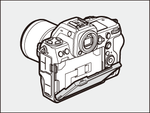
Camera Body
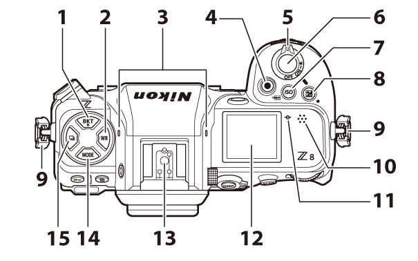
- BKT button (D; 0 Bracketing)
- WB button (U; 0 White Balance)
- Stereo microphone (0 Recording Videos)
- Video-record button (0 Recording Videos)
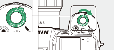
- Power switch (0 Camera Setup)
- Shutter-release button (0 Taking Photographs)
ISO sensitivity button (S; 0 ISO Sensitivity)
FORMAT button (Q; 0 The Format Buttons)
- Exposure compensation button (E; 0 Exposure Compensation)
- Eyelet for camera strap (0 Attaching the Strap)
- Speaker
- Focal plane mark (E; 0 The Focal Plane Mark and Flange-Back Distance)
- Control panel (0 The Control Panel, The Control Panel)
- Accessory shoe (for optional flash unit; 0 Using an On-Camera Flash, Compatible Flash Units)
- MODE button (I; 0 Choosing a Shooting Mode)
- Release mode button (c; 0 Release Mode)
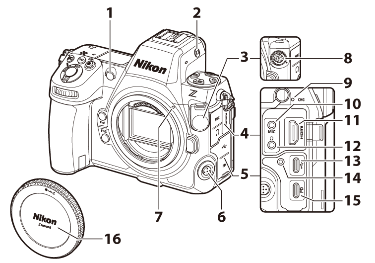
AF-assist illuminator (0 The AF-Assist Illuminator, a12: Built-in AF-Assist Illuminator)
Red-eye reduction lamp (0 Flash Modes)
Self-timer lamp (0 Using the Self-Timer (E))
- Monitor mode button (M; 0 The Monitor Mode Button and the Eye Sensor, Limit Monitor Mode Selection)
- Ten-pin remote terminal cover
- Cover for microphone, headphone, and HDMI connectors
- USB connector cover
- Focus-mode button (0 Focus Mode)
- Lens mounting mark (0 Attaching a Lens)
- Ten-pin remote terminal (0 Remote Terminal Accessories)
- Charge lamp (0 Optional EH‑7P Charging AC Adapters/EH‑8P AC Adapters: Charging)
- Connector for external microphone (0 Microphones)
- HDMI connector (0 Connecting to HDMI Devices)
- Headphone connector (0 Headphone Volume)
- USB data connector (0 Computers: Connecting via USB)
- Threaded hole for HDMI/USB cable clip (0 The HDMI/USB Cable Clip)
- USB Power Delivery connector (0 USB Power Delivery)
- Body cap (0 Attaching a Lens)
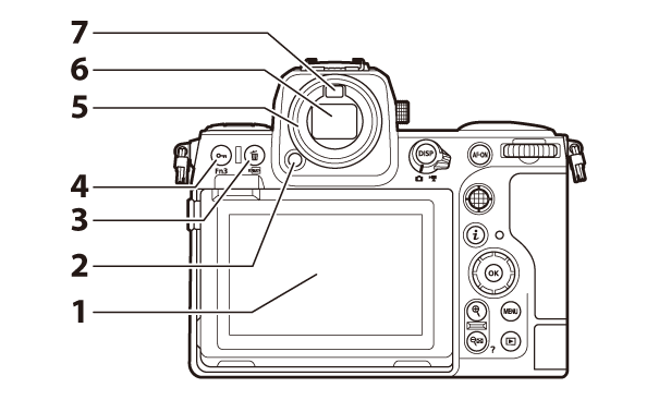
- Monitor (0 Touch Controls, The Touch Shutter)
- Eyepiece release (0 Viewfinder Eyepiece Accessories)
Delete button (O; 0 Deleting Unwanted Pictures, Deleting Pictures)
FORMAT button (Q; 0 The Format Buttons)
Protect button (g; 0 Protecting Pictures from Deletion)
Fn3 button (l; 0 Picture Controls)
- Rubber eyecup (0 Viewfinder Eyepiece Accessories)
- Viewfinder (0 The Viewfinder)
- Eye sensor (0 The Monitor Mode Button and the Eye Sensor)
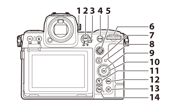
- Diopter adjustment control (0 The Diopter Adjustment Control)
- DISP button (d; 0 Choosing a Display)
- Photo/video selector (0 Taking Photographs, Recording Videos)
- AF-ON button (B; 0 Locking Focus with the AF‑ON Button)
- Sub-selector (0 The Sub-Selector, Focus Lock, Autoexposure Lock)
- Main command dial
- “i” button (i; 0 The i Button (i Menu), The i Button (Playback Mode))
- Memory card access lamp (0 The Memory Card Access Lamp, The Memory Card Access Lamp)
- OK button (J; 0 Using the Menus)
- Multi selector (0 Using the Menus)
- Playback zoom in button (X; 0 Manual Focus, Thumbnail Playback, Playback Zoom)
- MENU button (G; 0 The MENU Button)
- Playback button (K; 0 Playback, Viewing Pictures)
Playback zoom out/thumbnails button (W; 0 Thumbnail Playback, Using Playback Zoom)
Help button (Q; 0 The d (Help) Icon)
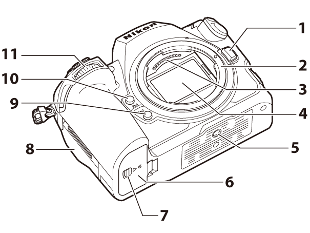
- Lens release button (0 Detaching Lenses)
- Lens mount (0 Attaching a Lens, The Focal Plane Mark and Flange-Back Distance)
- CPU contacts
- Image sensor (0 Image Sensor Cleaning)
- Tripod socket
- Battery chamber cover
- Battery chamber cover latch
- Memory card slot cover (0 Inserting Memory Cards)
- Fn2 button (k; 0 The Fn1 and Fn2 Buttons)
- Fn1 button (j; 0 The Fn1 and Fn2 Buttons)
- Sub-command dial
Do Not Touch the Image Sensor or Sensor Shield
Under no circumstances should you poke or exert pressure on the image sensor or sensor shield (0Sensor Shield Behavior at Power Off) or subject them to powerful air currents from a blower. Failure to observe this precaution could scratch or otherwise damage the sensor or shield. For information on cleaning the image sensor, see “Image Sensor Cleaning” (0Image Sensor Cleaning).
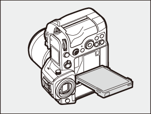
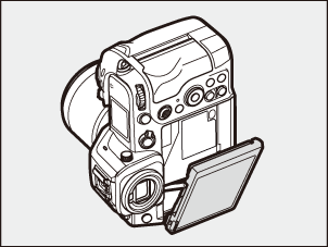
The angle of the monitor can be adjusted.
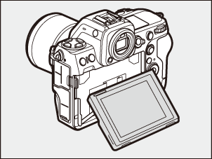
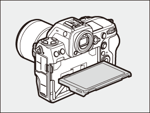

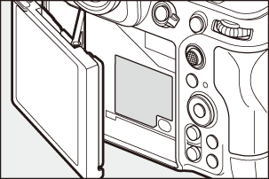
The serial number for this product can be found by opening the monitor.
Rotating the power switch to D activates the backlights for the buttons and control panels (LCD illuminator). The backlights will remain lit for a few seconds after the power switch is released. The backlights turn off when the switch is rotated to D a second time or the shutter-release button is pressed halfway. Activating the button backlight makes the camera easier to use in the dark.