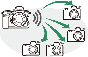
Synchronized Release
Configuring and Using Synchronized Release
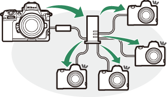
Follow the steps below to create host profiles for synchronized release. Each camera saves the pictures it takes to its own memory card. Repeat the process to create identical profiles for each camera.
Wireless LAN
To create host profiles when connecting via wireless LAN:
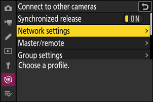
Select [Connect to other cameras] in the network menu, then highlight [Network settings] and press 2.
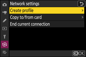
Highlight [Create profile] and press J.
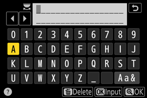
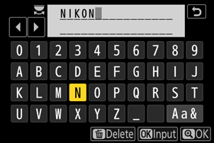
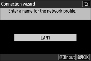
Name the new profile.
- To proceed to the next step without changing the default name, press X.
- Whatever name you choose will appear in the network menu [Connect to other cameras] > [Network settings] list.
- To rename the profile, press J. For information on text entry, see “Text Entry” (0 Text Entry). Press X to proceed after entering a name.

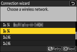
Highlight [Search for Wi-Fi network] and press J.
The camera will search for networks currently active in the vicinity and list them by name (SSID).
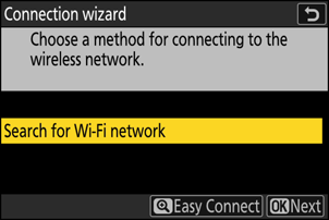
To connect without entering an SSID or encryption key, press X in Step 4. Next, highlight one of the following options and press J.

Option Description [Push-button WPS] For routers that support push-button WPS. Press the WPS button on the router and then press the camera J button to connect. [PIN-entry WPS] The camera will display a PIN. Using a computer, enter the PIN on the router. For more information, see the documentation provided with the router. - After connecting, proceed to Step 7.
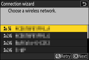
Choose a network.
- Highlight a network SSID and press J.
- The SSIDs containing characters that cannot be entered on the camera will not be displayed.
- The band on which each SSID operates is indicated by an icon.
- Encrypted networks are indicated by a h icon. If the selected network is encrypted (h), you will be prompted to enter the encryption key. If the network is not encrypted, proceed to Step 7.
- If the desired network is not displayed, press X to search again.
Hidden SSIDs
Networks with hidden SSIDs are indicated by blank entries in the network list.
- To connect to a network with a hidden SSID, highlight a blank entry and press J. Next, press J; the camera will prompt you to provide an SSID.
- Enter the network name and press X. Press X again; the camera will now prompt you to enter the encryption key.
Enter the encryption key.
- Press J and enter the encryption key for the wireless router.
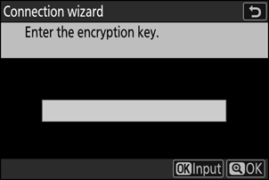
- For more information, see the documentation for the wireless router.
- Press X when entry is complete.
- Press X again to initiate the connection. A message will be displayed for a few seconds when the connection is established.

Obtain or select an IP address.
Highlight one of the following options and press J.

Option Description [Obtain automatically] Select this option if the network is configured to supply the IP address automatically. A “configuration complete” message will be displayed once an IP address has been assigned.
- It is recommended that you note the remote camera IP address, as you will need it in subsequent steps.
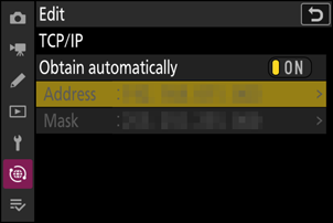
[Enter manually] Enter the IP address and sub-net mask manually.
- Press J; you will be prompted to enter the IP address.
- Rotate the main command dial to highlight segments.
- Press 4 or 2 to change the highlighted segment and press J to save changes.
- Next, press X; a “configuration complete” message will be displayed. Press X again to display the sub-net mask.
- Press 1 or 3 to edit the sub-net mask and press J; a “configuration complete” message will be displayed.
Press J to proceed when the “configuration complete” message is displayed.
The profile name is displayed when a connection is established.
Highlight [Master/remote] and press 2.
Choose a role for each camera from “master” and “remote”.
- [Master camera]: Pressing the shutter-release button on the master camera releases the shutters on the remote cameras. Each group can have only one master. If the group has multiple master cameras, only the first to connect to the network will actually serve in that capacity.
- [Remote camera]: The shutters on the remote cameras are synchronized with the shutter on the master camera.

Repeat Steps 1 through 9 for the remaining cameras.
When configuring remote cameras, be sure to select [Remote camera] in Step 9.
On the master camera, highlight [Group settings] and press 2.

Highlight [New] and press J.

Enter a group display name.
- Set a group display name to add remote cameras. Display names can be up to 32 characters long.
- Press X to proceed once entry is complete.
Highlight [Group name], press 2, and enter a group name.
Enter a group name for the synchronized cameras. Group names can be up to eight characters long.

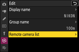
Highlight [Remote camera list] and press 2.
Add remote cameras to the group. The master camera can store information for up to 16 remote cameras in slots [01] through [16].
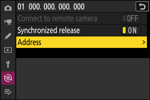
Highlight the desired slot and press 2.
Remote camera options will be displayed.

Highlight [Address] and press 2.
You will be prompted to enter an IP address.
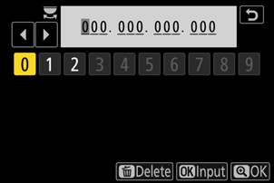
Enter the remote camera IP address.
Enter the remote camera IP address you noted in Step 7.
- Rotate the main command dial to highlight segments.
- Press 4 or 2 to change the highlighted segment and press J to save changes.
- Press X to add the remote camera to the master camera remote camera list and establish a connection.
Add the remaining remote cameras.
- When connecting to wireless networks, the cameras will display the band used by the selected SSID.
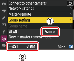
The master camera shows the group display name (q) selected in Step 13 as well as the number of remote cameras connected and not yet connected (w).
Take pictures.
A k icon appears in the master camera shooting display together with the number of remote cameras connected.
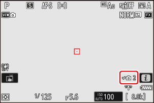
Pressing the shutter-release button on the master camera releases the shutters on the remote cameras.

Ethernet
Follow the steps below to create host profiles for Ethernet connections. A USB (Type C) to Ethernet adapter (available separately from third-party sources) is required for Ethernet connections. Be sure to connect the adapter to the camera’s USB data connector.
The following USB-to-Ethernet adapters have been tested and approved for use:
- Anker A83130A1 PowerExpand USB‑C to Gigabit Ethernet adapters
- Anker A83130A2 PowerExpand USB‑C to Gigabit Ethernet adapters
- Note that USB-to-Ethernet adapters will not function when connected to the camera’s USB Power Delivery connector.
Connect to other cameras via a third-party USB (Type C) to Ethernet adapter connected to the camera’s USB data connector.
Attach a third-party USB-to-Ethernet adapter to the camera’s USB data connector and then connect to a router using an Ethernet cable.
- Connect the Ethernet cable to the USB-to-Ethernet adapter. Do not use force or attempt to insert the connectors at an angle.
Connect the other end of the cable to a router.

- Connect the remaining cameras to the router using Ethernet cables.
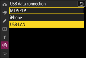
Select [USB-LAN] for [USB data connection] in the network menu.
Select [Connect to other cameras] in the network menu, then highlight [Network settings] and press 2.
Highlight [Create profile] and press J.
Name the new profile.
- To display IP address options without changing the default name, press X.
- Whatever name you choose will appear in the network menu [Connect to other cameras] > [Network settings] list.
- To rename the profile, press J. For information on text entry, see “Text Entry” (0 Text Entry). Press X to proceed after entering a name.
- There may be a delay before the camera detects the USB-to-Ethernet adapter. If the camera is unable to detect an Ethernet connection, the wizard will be configured to begin creation of a wireless LAN profile with the default name “WLAN1”. Tap Z or press 4 to return to Step 4, wait about 10 seconds, and then try again.
Obtain or select an IP address.
Highlight one of the following options and press J.
Option Description [Obtain automatically] Select this option if the network is configured to supply the IP address automatically. A “configuration complete” message will be displayed once an IP address has been assigned.
- It is recommended that you note the remote camera IP address, as you will need it in subsequent steps.
[Enter manually] Enter the IP address and sub-net mask manually.
- Press J; you will be prompted to enter the IP address.
- Rotate the main command dial to highlight segments.
- Press 4 or 2 to change the highlighted segment and press J to save changes.
- Next, press X; a “configuration complete” message will be displayed. Press X again to display the sub-net mask.
- Press 1 or 3 to edit the sub-net mask and press J; a “configuration complete” message will be displayed.
Press J to proceed when the “configuration complete” message is displayed.
The camera will initiate the connection. The profile name is displayed when a connection is established.
Highlight [Master/remote] and press 2.
Choose a role for each camera from “master” and “remote”.
- [Master camera]: Pressing the shutter-release button on the master camera releases the shutters on the remote cameras. Each group can have only one master. If the group has multiple master cameras, only the first to connect to the network will actually serve in that capacity.
- [Remote camera]: The shutters on the remote cameras are synchronized with the shutter on the master camera.

Repeat Steps 3 through 8 for the remaining cameras.
- To configure another Z 8 for use as a remote camera, repeat Steps 2 through 8.
- When configuring remote cameras, be sure to select [Remote camera] in Step 8.
On the master camera, highlight [Group settings] and press 2.

Highlight [New] and press J.
Enter a group display name.
- Set a group display name to add remote cameras. Display names can be up to 32 characters long.
- Press X to proceed once entry is complete.
Highlight [Group name], press 2, and enter a group name.
Enter a group name for the synchronized cameras. Group names can be up to eight characters long.
Highlight [Remote camera list] and press 2.
Add remote cameras to the group. The master camera can store information for up to 16 remote cameras in slots [01] through [16].
Highlight the desired slot and press 2.
Remote camera options will be displayed.
Highlight [Address] and press 2.
You will be prompted to enter an IP address.
Enter the remote camera IP address.
Enter the remote camera IP address you noted in Step 6.
- Rotate the main command dial to highlight segments.
- Press 4 or 2 to change the highlighted segment and press J to save changes.
- Press X to add the remote camera to the master camera remote camera list and establish a connection.
Add the remaining remote cameras.
The master camera shows the group display name (q) selected in Step 12 as well as the number of remote cameras connected and not yet connected (w).

Take pictures.
A k icon appears in the master camera shooting display together with the number of remote cameras connected.

Pressing the shutter-release button on the master camera releases the shutters on the remote cameras.

Suspending Synchronized Release
To temporarily disable synchronized release without ending the camera’s connection to the network, select [OFF] for [Connect to other cameras] > [Synchronized release] in the network menu.
To view remote camera status, go to [Connect to other cameras] > [Group settings] > (group display name) in the master camera network menu, highlight [Remote camera list], and press 2.
- Remote cameras are identified by IP address.
Remote camera status is displayed as follows:
- [Connected]: Normal connection.
- [Busy]: The camera is being controlled from another master camera.
[Error]: One of the following errors has been detected:
- The remote camera standby timer has expired.
- The remote camera is off.
- The remote camera is not in the same group as the master camera.
- The IP address is incorrect.
[OFF]: Either
- no remote camera has been assigned to the slot, or
- [OFF] is selected for [Connect to remote camera] on the camera in question.
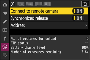
- Highlighting a remote camera with the [Connected] label and pressing 2 displays the number of pictures awaiting upload from the camera via FTP, FTP connection status, the battery level, and the number of exposures remaining.
- The entries for the remote cameras previously used for synchronized release will show the time of the most recent shot.

To edit remote camera settings from the master camera, highlight the camera in the remote camera list and press 2.
- To temporarily suspend the connection to the selected camera, select [OFF] for [Connect to remote camera].
- To temporarily suspend synchronized release on the selected camera, select [OFF] for [Synchronized release].
- If desired, you can then edit the camera’s IP address by highlighting [Address] and pressing 2. To reconnect, select [ON] for [Connect to remote camera]. No connection will be established if no remote camera exists at the specified address.
Saving Group Settings to a Memory Card
Navigate to [Connect to other cameras] > [Group settings] > [Copy to/from card] in the network menu, highlight [Copy to card], press 2, and then highlight group settings you wish to save and press 2 again. Select the destination (1–99) and press J to copy the group settings to the memory card. Saved group settings can be loaded using [Copy from card].