Other Accessories
A variety of accessories are available for your Nikon camera.
| Power sources |
|
|---|---|
| Filters |
|
| Mount adapters | FTZ Mount Adapter (0 FTZ Mount Adapter User’s Manual) |
| Remote cords | MC-DC2 Remote Cord (length 1 m/3 ft 4 in.): When connected to the camera accessory terminal, the MC-DC2 can be used to release the shutter remotely. |
| GPS units | GP-1/GP-1A GPS Unit: When connected to the camera accessory terminal, existing GP-1/GP-1A units can be used to record the current latitude, longitude, altitude, and UTC (Universal Coordinated Time) with pictures taken with the camera. Note that production of GP-1/GP-1A units has ended. |
| USB cables |
|
| HDMI cables | HC-E1 HDMI Cable: An HDMI cable with a type C connector for connection to the camera and a type A connector for connection to HDMI devices. |
| Hot shoe adapters | AS-15 Sync Terminal Adapter: Mount the AS-15 on the camera hot shoe to connect studio strobe lights or other flash equipment via a sync terminal. |
| Accessory shoe covers | BS-1 Accessory Shoe Cover: A cover protecting the accessory shoe when no flash unit is attached. |
| Body caps | BF-N1 Body Cap: The body cap prevents dust entering the camera when a lens is not in place. |
| Wireless transmitters |
WT-7 Wireless Transmitter: Use the WT-7 to upload pictures over a wireless network, to control the camera from a computer running Camera Control Pro 2 (available separately), or to take and browse pictures remotely from a computer or smart device. Note: A wireless network and some basic network knowledge is required when using a wireless transmitter. Be sure to update the wireless transmitter software to the latest version. |
| Wireless remote controllers |
Note: Be sure the firmware for the WR-R10 and WR-1 has been updated to the latest version (WR-R10 firmware version 3.0 or later and WR-1 firmware version 1.0.1 or later). For information on firmware updates, see the Nikon website for your area. Consult a Nikon-authorized service representative when updating the firmware for the WR-R10 from versions prior to version 2.0 to version 3.0 or later. |
| Viewfinder eyepiece accessories |
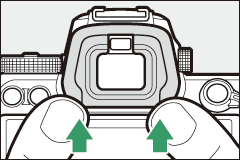
DK-29 Rubber Eyecup: The DK-29 makes the image in the viewfinder easier to see, preventing eye fatigue.
|
| Microphones |
|
| Software |
Camera Control Pro 2: Control the camera remotely from a computer and save photographs directly to the computer hard disk. When Camera Control Pro 2 is used to capture photographs directly to the computer, a PC connection indicator (PC) will appear in the control panel. Note: Use the latest versions of Nikon software; see the Nikon website for your region for the latest information on supported operating systems. At default settings, Nikon Message Center 2 will periodically check for updates to Nikon software and firmware while you are logged in to an account on the computer and the computer is connected to the Internet. A message is automatically displayed when an update is found. |
Availability may vary with country or region. See our website or brochures for the latest information.
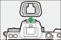
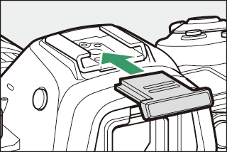
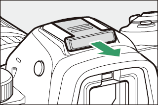
Attaching and Removing the Accessory Shoe Cover
The BS-1 accessory shoe cover slides into the accessory shoe as shown. To remove the cover, hold the camera firmly, press the cover down with a thumb and slide it in the direction shown.
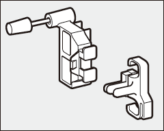
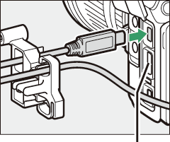
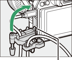
The HDMI/USB Cable Clip
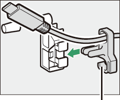
To prevent accidental disconnection, attach the supplied clip to HDMI cables or to the supplied USB cable as shown (the illustration shows the USB cable; note that the clip may not fit all third-party HDMI cables). Keep the monitor in the storage position when using the cable clip.

HDMI cable goes here
HDMI cable goes here
HDMI cable goes here
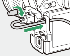
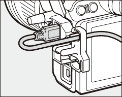
Insert tab into matching slot on camera and attach cable clip
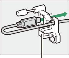
USB cable
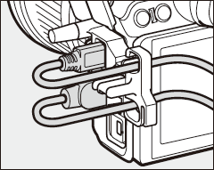
HDMI cable and USB cable used simultaneously
Attaching a Power Connector and AC Adapter
Turn the camera off before attaching an optional power connector and AC adapter.
-
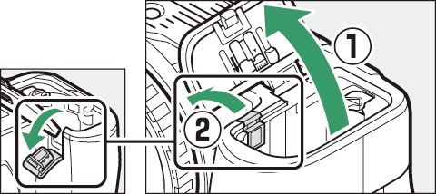
Ready the camera.
Open the battery-chamber (q) and power connector (w) covers.
-
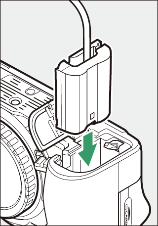
Insert the EP-5B power connector.
Be sure to insert the connector in the orientation shown, using the connector to keep the orange battery latch pressed to one side. The latch locks the connector in place when the connector is fully inserted.
-
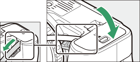
Close the battery-chamber cover.
Position the power connector cable so that it passes through the power connector slot and close the battery-chamber cover.
-
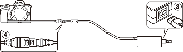
Connect the EH-5c/EH-5b AC adapter.
Connect the AC adapter power cable to the AC socket on the AC adapter (e) and the power cable to the DC socket (r). A P icon is displayed when the camera is powered by the AC adapter and power connector.