Compatible Accessories
A variety of accessories are available for your Nikon camera.
-
Availability may vary with country or region.
-
See our website or brochures for the latest information.
-
EN-EL18d Rechargeable Li-ion Battery: EN-EL18d batteries can be used with Nikon Z 9 digital cameras.
-
EN-EL18c, EN-EL18b, EN-EL18a, and EN-EL18 batteries can also be used. Note, however, that fewer pictures can be taken on a single charge than with the EN-EL18d (Battery Endurance).
-
-
MH-33 Battery Charger: The MH-33 can be used to recharge EN-EL18d batteries. Batteries can be charged while the charger is connected to a power source via the EH-7P charging AC adapter.
-
EH-7P Charging AC Adapter: The EH-7P can be used to charge batteries inserted in the camera.
-
The battery will not charge while the camera is on.
-
Charging AC adapters cannot be used to charge EN-EL18a or EN-EL18 batteries.
-
The charging AC adapter can be used to power the camera; to do so, select [] for [] in the setup menu. For more information, see “USB Power Delivery” (USB Power Delivery).
-
-
EP-6a Power Connector, EH-6d AC Adapter: Use AC adapters to power the camera for extended periods.
-
The EP-6a is needed to connect the EH-6d to the camera. See “Attaching a Power Connector and AC Adapter” (Attaching a Power Connector and AC Adapter) for details.
-
EH-6c, EH-6b, EH-6a, and EH-6 AC adapters can be used in place of the EH‑6d.
-
-
Neutral Color (NC) filters can be used to protect the lens.
-
Filters may cause ghosting when the subject is framed against a bright light, or when a bright light source is in the frame. Filters can be removed if ghosting occurs.
-
Matrix metering may not produce the desired results with filters with exposure factors (filter factors) over 1× (Y44, Y48, Y52, O56, R60, X0, X1, C‑PL, ND2S, ND4, ND4S, ND8, ND8S, ND400, A2, A12, B2, B8, B12); we suggest that [] be selected instead. See the documentation provided with the filter for details.
-
Filters intended for special-effects photography may interfere with autofocus or the in-focus indicator (I).
The camera is equipped with a ten-pin remote terminal for remote control and automatic photography.
Be sure to replace the terminal cap when the terminal is not in use. Dust or other foreign matter accumulating in the terminal contacts could cause the camera to malfunction.
-
MC-22/MC-22A Remote Cords (length approximately 1 m/3.3 ft): Remote shutter releases with blue, yellow, and black terminals for connection to remote shutter-triggering devices, allowing control via sound or electronic signals.
-
MC-30/MC-30A Remote Cords (length approximately 80 cm/2.7 ft): Remote shutter releases; can be used to reduce camera shake.
-
MC-36/MC-36A Remote Cords (length approximately 85 cm/2.8 ft): Remote shutter releases with timers for interval-timer photography.
-
MC-21/MC-21A Extension Cords (length approximately 3 m/9.9 ft): Can be connected to ML-3 or MC-series 20, 22, 22A, 23, 23A, 25, 25A, 30, 30A, 36, or 36A, but note that two or more extension cords cannot be connected together.
-
MC-23/MC-23A Connecting Cords (length approximately 40 cm/1.4 ft): Use an MC-23 or 23A to connect two cameras via their ten-pin terminals for simultaneous operation.
-
MC-25/MC-25A Adapter Cords (length approximately 20 cm/7.9 in.): Ten-pin to two-pin adapter cords for connection to devices with two-pin terminals, including the MW-2 radio control set, MT-2 intervalometer, and ML-2 modulite remote control set.
-
WR-A10 WR Adapter: An adapter used to connect WR-R10 wireless remote controllers to cameras with ten-pin remote terminals.
-
ML-3 Modulite Remote Control Set: Allows infrared remote control at ranges of up to 8 m (26.2 ft).
-
UC-E24 USB Cable: A USB cable with a type C connector for connection to the camera and a type A connector for connection to the USB device.
-
UC-E25 USB Cable: A USB cable with two type C connectors.
BS-1 Accessory Shoe Cover: A cover protecting the accessory shoe when no flash unit is attached.
BF-N1 Body Cap: The body cap prevents dust entering the camera when no lens is in place.
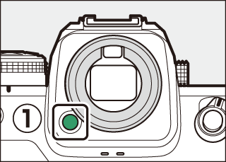
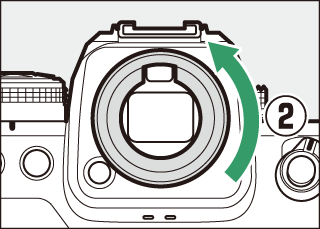
DK-33 Rubber Eyecup: A rubber eyecup that comes fitted to the camera. It can be removed by holding the eyepiece release (q) and rotating the eyecup in the direction shown (w).
|
|
|
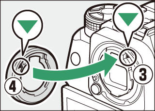
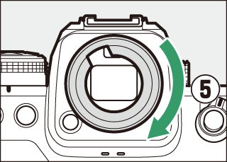
To re-attach the eyecup, align the mark on the rear of the eyecup (r) with the mark on the camera body (e) and rotate the eyecup as shown until it clicks into place (t).
|
|
|
-
SB-5000, SB-910, SB-900, SB-800, SB-700, SB-600, SB-500, SB-400, SB‑300, and SB-R200 Speedlights: These units can be mounted on the camera for flash photography. Some also support wireless remote control for off-camera flash photography with multiple flash units.
-
See the documentation supplied with each Speedlight for information on mounting the unit on the camera.
-
For more information on flash photography, see “Flash Photography” (Flash Photography), “Remote Flash Photography” (Remote Flash Photography), and “Compatible Flash Units” (Compatible Flash Units).
-
-
SU-800 Wireless Speedlight Commander: A wireless commander for use with SB-5000, SB-910, SB-900, SB-800, SB-700, SB-600, SB-500, and SB-R200 flash units. Flash units can be divided into up to three groups for remote flash control. The SU-800 itself is not equipped with a flash.
FTZ II/FTZ Mount Adapter: An adapter that allows NIKKOR F mount lenses to be used with digital cameras that support interchangeable Z mount lenses.
-
For information on attaching, removing, maintaining, and using mount adapters, refer to the product documentation.
-
Update to the latest version of the mount adapter firmware if so prompted after attaching the adapter. Information on performing firmware updates is available via the Nikon website for your country or region.
-
-
Users of the FTZ should note that the lack of space between adapter and grip can make the grip difficult to use.
-
ME-1 Stereo Microphone: Connect the ME-1 to the camera microphone jack to record stereo sound. Using an external microphone also reduces the chance of picking up equipment noise, such as the sounds produced during video recording when focus is achieved using autofocus.
-
ME-W1 Wireless Microphone: A wireless Bluetooth microphone. Use the ME-W1 for off-camera recording.
-
WR-R11a, WR-R10, and WR-T10 Wireless Remote Controllers
-
When a WR-R11a is connected to the ten-pin remote terminal, or when a WR-R10 is connected to the ten-pin remote terminal using a WR-A10 adapter, the camera can be controlled remotely using a WR-T10 wireless remote controller.
-
WR-R11a and WR-R10 wireless remote controllers can also be used to control radio-controlled flash units.
-
-
WR-1 Wireless Remote Controller: WR-1 units are used with WR-R11a/WR-R10 or WR-T10 wireless remote controllers or with other WR-1 remote controllers, with the WR-1 units functioning as either transmitters or receivers. When a WR-R11a/WR-R10 or a WR-1 configured as a receiver is connected to the camera ten-pin remote terminal, a second WR-1 configured as a transmitter can be used to take pictures and adjust camera settings remotely. Update the WR‑1 firmware to the latest version (version 1.0.4 or later).
-
When using a wireless remote controller with the WR-R10, be sure the firmware for the WR-R10 has been updated to the latest version (version 3.0 or later). For information on firmware updates, see the Nikon website for your area. Consult a Nikon-authorized service representative when updating the firmware for the WR-R10 from versions prior to version 2.0 to version 3.0 or later.
-
MC-N10 Remote Grip: When connected to the camera, the MC-N10 can be used for such tasks as video recording, photography, and adjusting camera settings. It comes equipped with a rosette for attachment to third-party camera equipment. With the MC-N10 mounted on third-party camera equipment via an ARRI-compatible rosette adapter, you can keep moving subjects in focus while panning the camera to track their motion, or use its conveniently-placed controls to adjust settings such as exposure and white balance without touching the camera.
Compatible batteries can be charged using the devices below.
|
Battery |
Battery charger |
Charging AC adapter |
|
|---|---|---|---|
|
MH-33 |
MH-26a |
||
|
EN-EL18d |
4 |
— |
4 |
|
EN-EL18c |
4 |
4 |
4 |
|
EN-EL18b |
4 |
4 |
4 |
|
EN-EL18a |
— |
4 |
— |
|
EN-EL18 |
— |
4 |
— |
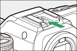
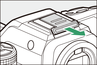
The BS-1 accessory shoe cover slides into the shoe as shown. To remove the cover, hold the camera firmly, press the cover down with a thumb and slide it in the direction shown.
|
|
|
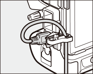
To prevent accidental disconnection, attach the supplied clip to HDMI or USB cables as shown (note that the clip may not fit all cables).
-
The illustrations show the USB cable. Pass HDMI cables through the other channel.
-
Keep the monitor in the storage position when using the cable clip.
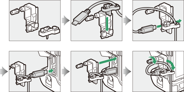
USB cable
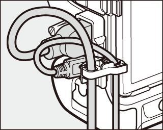
HDMI cable and USB cable used simultaneously
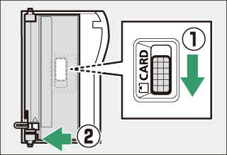
The camera features a removable memory card slot cover.
-
After opening the memory card slot cover, slide the memory card slot cover release latch in the direction shown until it latches (q) and then remove the cover from the camera (w).
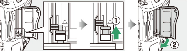
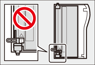
-
Be careful not to slide the memory card slot cover release latch back down after removing the memory card slot cover. The cover cannot be re-attached with the latch lowered.
-
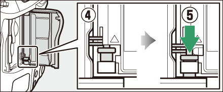
The inner cover may move when the memory card slot cover release latch is lowered. The memory card slot cover cannot be reattached when the inner cover is out of position. Slide the memory card slot cover latch down (q) and restore the inner and outer covers to their original positions (w).
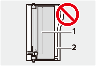
1 Inner cover
2 Outer cover
-
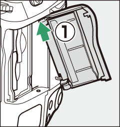
To re-attach the memory card slot cover, follow the steps below.
-
Insert the top hinge into the top socket on the camera body (q).
-
Insert the end of the sprung hinge (e) into the hinge socket (w).
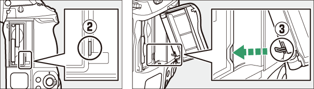
-
Keeping the bottom hinge aligned with the bottom socket (r), slide the memory card slot cover release latch down until it clicks into place in its original position (t).
-
Calibrating Batteries
The MH-33 battery charger can detect whether batteries require calibration and calibrate them as necessary to ensure the accuracy of the battery level display.
Calibration status and progress are shown by lamps on the battery charger:
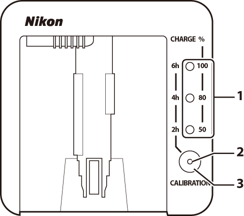
| 1 |
Charge lamps |
|---|---|
| 2 |
Calibration lamp |
| 3 |
Calibration button |
|---|
If the calibration lamp flashes when a battery is inserted, the battery needs to be calibrated.
To begin calibration, press the calibration button for about a second. The charge lamps and calibration lamp light red while calibration is in progress. The display can be read as follows:
|
Approximate time needed to recalibrate battery |
|||||
|---|---|---|---|---|---|
|
Under 2 hours |
2–4 hours |
4–6 hours |
Over 6 hours |
||
|
Charge lamps |
2h |
I (off) |
K (on) |
K (on) |
K (on) |
|
4h |
I (off) |
I (off) |
K (on) |
K (on) |
|
|
6h |
I (off) |
I (off) |
I (off) |
K (on) |
|
|
Calibration lamp |
K (on) |
K (on) |
K (on) |
K (on) |
|
Although calibration is recommended for accurate measurement of battery charge state, calibration need not be performed when the calibration lamp flashes. Once begun, calibration can be interrupted as desired.
-
If the calibration button is not pressed while the calibration lamp is flashing, normal charging will begin after about ten seconds.
-
To interrupt calibration, press the calibration button again. Calibration will end and charging will begin.
When calibration is complete, the charge lamps and calibration lamp will turn off and charging will begin immediately.
Attaching a Power Connector and AC Adapter
Turn the camera off before attaching an optional power connector and AC adapter.
-
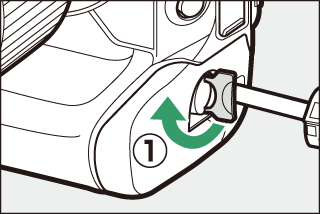
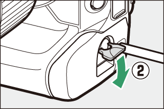
Remove the BL-7 battery chamber cover.
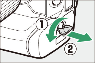
Lift the battery chamber cover latch, turn it to the open (A) position (q), and remove the BL-7 battery chamber cover (w).
-
Connect the EH-6d AC adapter to the EP-6a power connector.
-
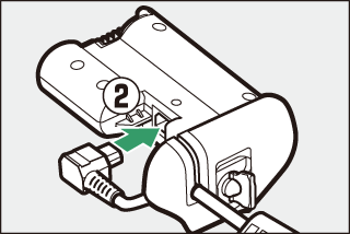
Pass the DC cable over the power connector cable guide (q) and slide it down until it is at the bottom of the slot.
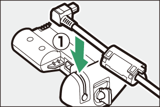
-
Insert the DC plug into the DC IN connector (w).
-
-
Insert the power connector.
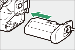
Fully insert the power connector into the battery chamber as shown.
-
Latch the power connector.
-
Rotate the latch to the closed position (q) and fold it down as shown (w).
-
To prevent the power connector being dislodged during operation, be sure that it is securely latched.
-
The battery level is not displayed in the control panel while the camera is powered by the AC adapter and power connector.
-