Other Compatible Accessories
A variety of accessories are available for your Nikon camera.
-
EN‑EL18c Rechargeable Li-ion Battery: EN‑EL18c batteries can be used with Nikon D6 digital cameras. EN-EL18c batteries can be charged and calibrated using MH-26a battery chargers.
-
EN‑EL18b/EN‑EL18a/EN‑EL18 batteries can also be used. Note, however, that fewer pictures can be taken on a single charge with an EN‑EL18 than with an EN‑EL18c/EN‑EL18b/EN‑EL18a (Battery Endurance).
-
-
MH-26a Battery Charger: The MH-26a can be used to recharge EN‑EL18c/EN‑EL18b/EN‑EL18a/EN‑EL18 batteries. The MH-26a can also be used to calibrate batteries.
-
MH-26 battery chargers can be used in place of the MH-26a.
-
-
EP-6 Power Connector, EH-6c AC Adapter: Use AC adapters to power the camera for extended periods.
-
The EP-6 is needed to connect the EH-6c to the camera. See “Attaching a Power Connector and AC Adapter” ( Attaching a Power Connector and AC Adapter ) for details.
-
EH-6b, EH-6a, and EH-6 AC adapters can be used in place of the EH-6c.
-
BS-3/BS-1 Accessory Shoe Covers: Accessory shoe covers protect the accessory shoe when no flash unit is attached (The BS-3 Accessory Shoe Cover).
BF-1B Body Cap/BF-1A Body Cap: Body caps prevent dust entering the camera when no lens is in place.
-
DK-19 Rubber Eyecup: A rubber eyecup that can be fitted to the camera viewfinder. The DK-19 makes the image in the viewfinder easier to see, preventing eye fatigue.
-
DK-17C Diopter-Adjustment Viewfinder Lenses: These lenses can be dropped into the viewfinder eyepiece to accommodate the needs of far- and near-sighted photographers. Choose from lenses with diopters of −3, −2, 0, +1, and +2 m−1. Be sure to try the lenses in the store before purchase, as results can vary widely from person to person. Diopter adjustment lenses (Attaching Diopter-Adjustment Viewfinder Lenses) can be used for diopters beyond the range of the camera’s diopter adjustment control (−3 to +1 m−1).
-
DK-17M Magnifying Eyepiece: When fitted to the camera viewfinder, the DK-17M increases magnification by approximately 1.2×.
-
DG-2 Eyepiece Magnifier: The DG-2 magnifies the scene at the center of the viewfinder. Use it in situations requiring especially precise focus.
-
DK-18 Eyepiece Adapter: An adapter used when attaching DG-2 magnifiers or DR-3 right-angle viewing attachments (Removing the Eyepiece Adapter).
-
DK-27 Eyepiece Adapter: A DK-27 is supplied with the camera.
-
DK-14/DK-17A Antifog Finder Eyepieces: These viewfinder eyepieces prevent fogging in humid or cold conditions.
-
DK-17F Fluorine-Coated Finder Eyepiece: A DK-17F is supplied with the camera. The protective glass features Nikon’s unique, easy-to-clean fluorine coating on both surfaces.
-
DR-5 Right-Angle Viewing Attachment: The DR-5 attaches to the viewfinder eyepiece at a right angle, allowing the image in the viewfinder to be viewed from above when the camera is used to take pictures in “wide” (landscape) orientation. Choose from magnifications of 1× and 2× *, the former to view the entire frame and the latter for greater precision when focusing. Diopter adjustment is also supported.
-
The edges of the frame are not visible when the view is magnified.
-
-
DR-4 Right-Angle Viewing Attachment: The DR-4 attaches to the viewfinder eyepiece at a right angle, allowing the image in the viewfinder to be viewed from above when the camera is used to take pictures in “wide” (landscape) orientation.
-
Neutral Color (NC) filters can be used to protect the lens.
-
The camera cannot be used with linear polarizing filters. Use the C-PL or C-PLII circular polarizing filter instead.
-
Filters may cause ghosting when the subject is framed against a bright light, or when a bright light source is in the frame. Filters can be removed if ghosting occurs.
-
RGB and 3D-RGB matrix metering may not produce the desired results with filters with exposure factors (filter factors) over 1× (Y44, Y48, Y52, O56, R60, X0, X1, C-PL, ND2S, ND4, ND4S, ND8, ND8S, ND400, A2, A12, B2, B8, B12); we suggest that [] be selected instead. See the filter manual for details.
-
Filters intended for special-effects photography may interfere with autofocus or the electronic rangefinder.
WT-6 Wireless Transmitters: Use a wireless transmitter to upload pictures over a wireless network or control the camera from a computer running Camera Control Pro 2 (available separately). You can also take and browse pictures remotely from a computer or smart device.
-
Requires a wireless network and some basic network knowledge. Be sure to update the wireless transmitter software to the latest version.
-
WT-5 wireless transmitters cannot be used.
-
WR-R10/WR-T10 Wireless Remote Controllers: When a WR-R10 is connected to the ten-pin remote terminal using a WR-A10 adapter, the camera can be controlled remotely using a WR-T10 wireless remote controller.
-
The WR-R10 can also be used to control radio-controlled flash units.
-
For synchronized release involving more than one camera, ready multiple cameras with paired WR-R10 units attached.
-
-
WR-1 Wireless Remote Controller: WR-1 units are used with WR-R10 or WR-T10 wireless remote controllers or with other WR-1 remote controllers, with the WR-1 units functioning as either transmitters or receivers. When a WR-R10 or a WR-1 configured as a receiver is connected to the ten-pin remote terminal, a WR-T10 or a second WR-1 configured as a transmitter can be used to take pictures remotely. Camera settings can also be adjusted using a WR-1 configured as a transmitter.
-
Be sure the firmware for the WR-R10 and WR-1 has been updated to the latest versions (WR-R10 firmware version 3.0 or later and WR-1 firmware version 1.0.1 or later). For information on firmware updates, see the Nikon website for your area. Consult a Nikon-authorized service representative when updating the firmware for the WR-R10 from versions prior to version 2.0 to version 3.0 or later.
The camera is equipped with a ten-pin remote terminal for remote control and automatic photography.
Be sure to replace the terminal cap when the terminal is not in use. Dust or other foreign matter accumulating in the terminal contacts could cause the camera to malfunction.
-
MC-22/MC-22A Remote Cords (length approximately 1 m/3.3 ft): Remote shutter releases with blue, yellow, and black terminals for connection to remote shutter-triggering devices, allowing control via sound or electronic signals.
-
MC-30/MC-30A Remote Cords (length approximately 80 cm/2.7 ft): Remote shutter releases; can be used to reduce camera shake.
-
MC-36/MC-36A Remote Cords (length approximately 85 cm/2.8 ft): Remote shutter releases with timers for interval-timer photography.
-
MC-21/MC-21A Extension Cords (length approximately 3 m/9.9 ft): Can be connected to ML-3 or MC-series 20, 22, 22A, 23, 23A, 25, 25A, 30, 30A, 36, or 36A, but note that two or more extensions cords cannot be connected together.
-
MC-23/MC-23A Connecting Cords (length approximately 40 cm/1.4 ft): Use an MC-23 or 23A to connect two cameras via their ten-pin terminals for simultaneous operation.
-
MC-25/MC-25A Adapter Cords (length approximately 20 cm/7.9 in.): Ten-pin to two-pin adapter cords for connection to devices with two-pin terminals, including the MW-2 radio control set, MT-2 intervalometer, and ML-2 modulite control set.
-
WR-A10 WR Adapter: An adapter used to connect WR-R10 wireless remote controllers to cameras with ten-pin remote terminals.
-
ML-3 Modulite Remote Control Set: Allows infrared remote control at ranges of up to 8 m (26.2 ft).
-
UC-E24 USB Cable: A USB cable with a type C connector for connection to the camera and a type A connector for connection to the USB device.
-
UC-E25 USB Cable: A USB cable with two type C connectors.
HC-E1 HDMI Cable: An HDMI cable with a type C connector for connection to the camera and a type A connector for connection to HDMI devices.
-
ME-1 Stereo Microphone: Connect the ME-1 to the camera microphone jack to record stereo sound. Using an external microphone also reduces the chance of picking up equipment noise, such as the sounds produced by the lens during autofocus.
-
ME-W1 Wireless Microphone: A wireless Bluetooth microphone. Use the ME-W1 for off-camera recording.
UF-6 Connector Cover for Stereo Mini-Plug Cables: Prevents accidental disconnection of mini-plug cables for optional ME-1 stereo microphones.
-
Availability may vary with country or region.
-
See our website or brochures for the latest information.
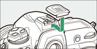
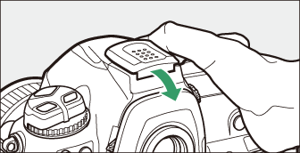
The supplied accessory shoe cover can be used to protect the accessory shoe or to prevent light reflected from the metal parts of the shoe appearing in photographs. The cover slides into the shoe as shown. To remove the cover, hold the camera firmly, press the cover down with a thumb and slide it in the direction shown.
|
|
|
Remove the DK-17F viewfinder eyepiece before attaching a diopter-adjustment viewfinder
lens. Press the latches on both sides of the eyepiece adapter simultaneously to release
the eyepiece lock (q) and then unscrew the eyepiece as shown (w).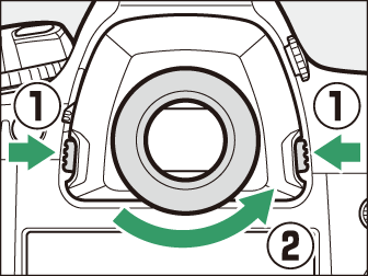
Press and lift the latches on both sides simultaneously (q) and remove the adapter as shown (w).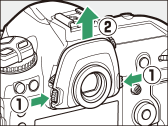
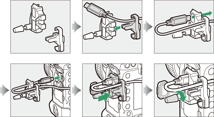
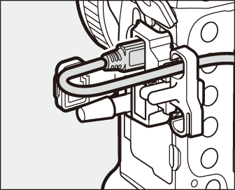
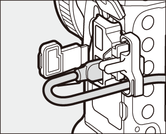
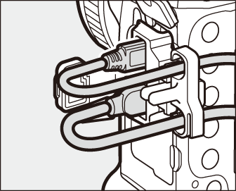
To prevent accidental disconnection, attach the supplied clip to HDMI cables or to the supplied USB cable as shown (note that the clip may not fit all third-party HDMI cables). The illustrations show the USB cable.
|
USB cable |
HDMI cable |
HDMI cable and USB cable used simultaneously |
Attaching a Power Connector and AC Adapter
Turn the camera off before attaching an optional power connector and AC adapter.
-
Remove the BL-6 battery-chamber cover.
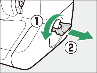
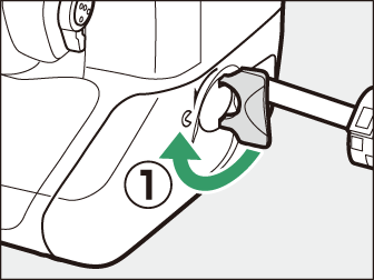
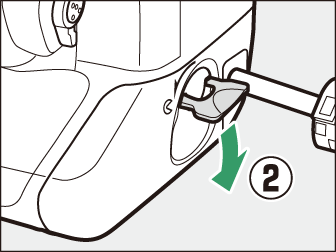
Lift the battery-chamber cover latch, turn it to the open (A) position (q), and remove the BL-6 battery-chamber cover (w).
-
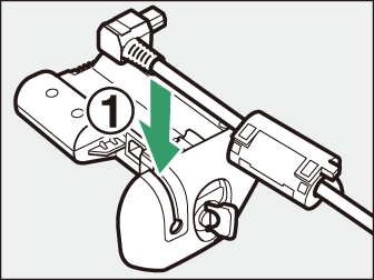
Connect the EH‑6c AC adapter to the EP-6 power connector.
-
Pass the DC cable over the power connector cable guide (q) and slide it down until it is at the bottom of the slot.
-
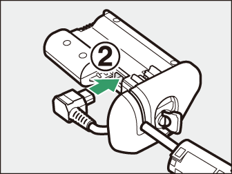
Insert the DC plug into the DC IN connector (w).
-
-
Insert the power connector.
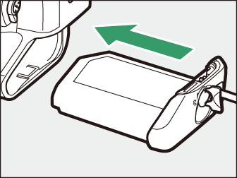
Fully insert the power connector into the battery chamber as shown.
-
Latch the power connector.
-
Rotate the latch to the closed position (q) and fold it down as shown (w).
-
To prevent the power connector being dislodged during operation, be sure that it is securely latched.
-
The battery level is not displayed in the top control panel while the camera is powered by the AC adapter and power connector.
-