Flash Info for Remote Units
The camera can display flash info for a SB-5000 or SB-500 flash unit mounted on the camera accessory shoe and configured as a master flash for optical AWL, as well as for remote flash units controlled via radio AWL using a WR-R10. To view flash info during viewfinder photography, press the R button to activate the information display (The Information Display) and then press the R button again.
Flash Control Mode Displays
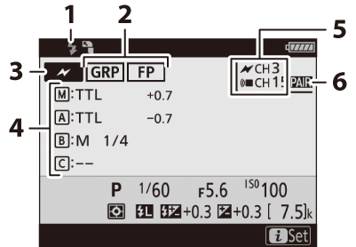
Group Flash
| 1 |
Flash-ready indicator 1 |
|---|---|
| 2 |
Remote flash control (Remote Flash Control) FP indicator ( e1: Flash Sync Speed ) |
| 3 |
Remote flash control mode 2 (Wireless Flash Options) |
| 4 |
Group flash control mode 3 Group flash mode (Group Flash, Group Flash) Flash compensation/flash level (output; Group Flash, Group Flash) |
|---|---|
| 5 |
Channel 2 (Establishing a Wireless Connection, Group Flash) |
| 6 |
Link mode 4 (Link Mode) |
Quick Wireless Control
| 1 |
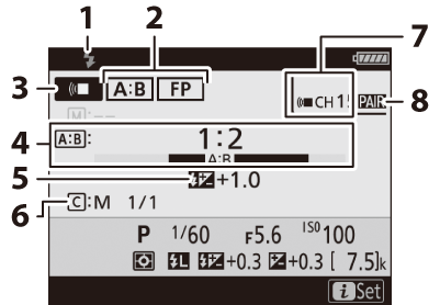
Flash-ready indicator 1 |
|---|---|
| 2 |
Remote flash control (Remote Flash Control) FP indicator ( e1: Flash Sync Speed ) |
| 3 |
Remote flash control mode 2 (Wireless Flash Options) |
| 4 |
A:B ratio (Quick Wireless Control, Quick Wireless Control (SB-5000 Only)) |
| 5 |
Flash compensation (Quick Wireless Control, Quick Wireless Control (SB-5000 Only)) |
|---|---|
| 6 |
Group C flash control mode and flash level (output; Quick Wireless Control, Quick Wireless Control (SB-5000 Only)) |
| 7 |
Channel 2 (Establishing a Wireless Connection, Quick Wireless Control (SB-5000 Only)) |
| 8 |
Link mode 4 (Link Mode) |
Remote Repeating
| 1 |
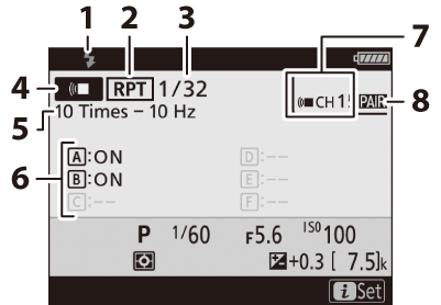
Flash-ready indicator 1 |
|---|---|
| 2 |
Remote flash control (Remote Flash Control) |
| 3 | |
| 4 |
Remote flash control mode 2 (Wireless Flash Options) |
| 5 |
Times (Remote Repeating, Remote Repeating (SB-5000 Only)) Frequency (Remote Repeating, Remote Repeating (SB-5000 Only)) |
|---|---|
| 6 |
Group status (enabled/disabled; Remote Repeating, Remote Repeating (SB-5000 Only)) |
| 7 |
Channel 2 (Establishing a Wireless Connection, Remote Repeating (SB-5000 Only)) |
| 8 |
Link mode 4 (Link Mode) |
-
Displayed in radio AWL when all flash units are ready.
-
Optical AWL is indicated by Y, radio AWL by Z, joint optical and radio AWL by both icons together. Optical AWL channel for joint optical and radio AWL is displayed only when SB-500 is used as master flash.
-
Icons are displayed for each group only when joint optical and radio AWL is used.
-
Displayed only when radio AWL or joint optical and radio AWL is used.
The flash information display shows select camera settings, including exposure mode,
shutter speed, aperture, and ISO sensitivity.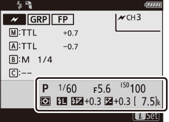
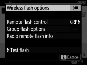
Flash settings can be changed by pressing the i button in the flash info display. The options available vary with the flash unit
and the settings selected. You can also test-fire the flash.